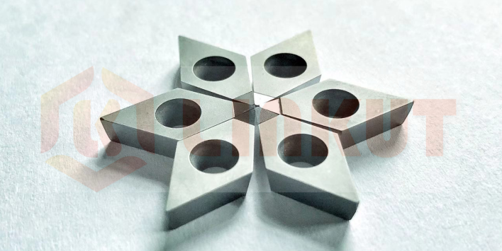
Common failure mode for PCD Tools
There are mainly 2 types failure mode for the PCD tools
1) Crater wear
The crater is commonly found in high-speed machining of iron-based or titanium-based alloys, which is a thermal or chemical problem in which the insert dissolves into the
workpiece's chips.The combination of diffusion wear and abrasive wear causes crater. In processing substrates and titanium-based alloys, the heat in the workpiece's chips
dissolves and diffuses the cemented carbide components into the chips, creating a "crater" on the top of the insert. The crater will eventually increase enough to cause
micro-collapse, deformation of the flank, and possibly even rapid flank wear.
2) Built-up edge
When the pieces of the workpiece are welded to the cutting edge by thermocompression bonding, a built-up edge occurs, which is caused by chemical affinity, high pressure
and high temperature in the cutting zone. The built-up edge eventually falls off and sometimes falls off with the insert fragments, resulting in micro-disintegration and rapid flank
wear.
This failure mechanism is common in viscous materials, low speed, high temperature alloys, stainless steel and non-ferrous materials, as well as threading and drilling. The
built-up edge can be identified by anomalous changes in the size or surface roughness of the workpiece and the shiny material that appears on the top or flank of the cutting edge.
The built-up edge can be controlled by increasing the cutting speed and feed rate, using a nitride (TiN) plating insert,, using a proper coolant (such as increasing the concentration),
and selecting a geometry with reduced force or A blade that smoothes the surface.
Previous Article:Why the straight type PCD wire drawing die with longer life?
Next Article: The Unsteady Factors of CBN Inserts for High Manganese Steel Machining


